Gateway Design
Schematic
The OpenTherm gateway circuitry consists of five major parts:- Power supply (X3, TR1, D1, D2, D3, D4, C1, C2, and IC3)
- Two voltages are needed: An unregulated voltage of around 24 Volts for
the Opentherm slave interface and a more accurate 5 Volts supply for the PIC
and the MAX232.
- OpenTherm master interface (X2, D5, D6, D7, D8, D9, D10, D11, Q1, OK1, R1, R2, R3, R4, and R8)
- The master interface behaves like an OpenTherm Room Unit / Master device
(thermostat). The master interface controls the voltage on the OpenTherm
connection and measures the current. The interface is galvanically isolated
from the rest of the device.
- OpenTherm slave interface (X1, Q2, Q3, Q4, Q5, R5, R6, R7, R9, R11, and R12)
- The slave interface behaves like an OpenTherm Boiler Unit / Slave device.
The slave interface drives the current on the OpenTherm connection and
measures the voltage.
- Control unit (IC1, R15, SV2, SV3, and JP1)
- The PIC16F88 or PIC16F1847 is the central intelligence of the OpenTherm
gateway. The reset line is normally held high by a resistor connected to VCC.
Several of the I/O pins are made available via headers. These can be used to
drive LEDS, hook up an outside temperature sensor, or connect a reset button.
- RS232 line driver (IC2, C4, C5, C6, C7, and SV1)
- For communicating with the outside world the TTL level serial signals from the PIC have to be converted to proper RS232 levels. This is done with a standard circuit around a MAX232 chip.

[High
resolution version (2134x1640)]
Notes:
- The actual voltage on the points marked "+24V" is not very critical. It should be somewhere between 20V (maximum Opentherm line voltage + a small margin for the line driver) and 35V (the maximum allowed input voltage for the LM7805).
- Q4 is necessary for keeping the voltage on pin 3 of IC1 below VDD.
- The schematic doesn't explicitly show it, but when designing your own print layout don't forget to connect the VCC and GND pins of IC2.
Part List
| Qty | Description | Value | Reference | Conrad Part No |
| 1 | PIC processor | PIC16F88P | IC1 | 165233-89 |
| 1 | RS232 interfacemodule | MAX232 | IC2 | 152281-89 |
| 1* | Voltage Regulator TO220 | MC7805CT | IC3 | 175030-89 |
| 1 | Dual opto-coupler | PC827 | OK1 | 140235-89 |
| 4 | PNP Transistor | BC558A | Q1, Q2, Q3, Q5 | 1262971-89 |
| 1 | NPN Transistor | BC547B | Q4 | 1262957-89 |
| 1 | Electrolytic Capacitor, Radial 63V | 220µF | C1 | 445902-89 |
| 1 | Electrolytic Capacitor, Radial 16V | 100µF | C2 | 445928-89 |
| 4 | Electrolytic Capacitor, Radial 50V | 1µF | C3, C4, C5, C6 | 445724-89 |
| 4 | Diode | 1N4004 | D1, D2, D3, D4 | 162248-89 |
| 4 | Diode | 1N4148 | D5, D6, D7, D8 | 162280-89 |
| 1 | Zener Diode | 4V7 | D9 | 180084-89 |
| 1 | Zener Diode | 15V | D10 | 180203-89 |
| 1 | Zener Diode | 4V3 | D11 | 180076-89 |
| 1 | 1/4 Watt 5% Resistor | 39 | R12 | 1417702-89 |
| 2 | 1/4 Watt 5% Resistor | 100 | R2, R11 | 1417639-89 |
| 1 | 1/4 Watt 5% Resistor | 220 | R3 | 1417693-89 |
| 2 | 1/4 Watt 5% Resistor | 330 | R1, R4 | 1417730-89 |
| 1 | 1/4 Watt 5% Resistor | 1k2 | R8 | 1417712-89 |
| 2 | 1/4 Watt 5% Resistor | 4k7 | R6, R9 | 1417695-89 |
| 1 | 1/4 Watt 5% Resistor | 15k | R10 | 1417711-89 |
| 2 | 1/4 Watt 5% Resistor | 33k | R5, R7 | 1417647-89 |
| 1* | Transformer EI30 | 15V 1.2VA | TR1 | 710691-89 |
| 1 | Header | 10 pin | SV1 | 741648-89 |
| 3 | Screw Clamp | 2 pin | X1, X2, X3 | 731091-89 |
| * In case you want to power an ESP8266-based device, such as a NodeMCU devkit board or Wemos D1 mini, from the same power supply, you may want to order these alternatives instead: | ||||
| 1 | Transformer EI30 | 15V 2VA | TR1 | 710564-89 |
| 1 | DC/DC convertor | R-78E5.0-0.5 | IC3 | 157954-89 |
Some more links to parts I used from Conrad:
- Enclosure, €4.58
- Connector set, €2.84
The PICs can also be ordered from Van Ooijen Technische Informatica (shipping within NL: €3.50). As a service for people who don't have their own programmer, this web shop offers to program the PIC for a small fee (€3.00).
- PIC16F88, €4.72
- PIC16F1847, €2.66
It may even be possible to get a programmed PIC
directly from Microchip (Enter PIC16F88-I/P or PIC16F1847-I/P, then
upload the gateway.hex file for the selected PIC).
They appear to charge €3.17 for a PIC16F88, €1.90 for a PIC16F1847,
€0.14 for programming. Shipping to the Netherlands used to be reasonably
priced at around €5.76, but is currently listed as €22.05.
If you try this method, please share your experiences so I can update the
above statement to a more definite version.
(Prices recorded Mar 9, 2022)
Assembly Sheet
An opentherm gateway user has prepared a drawing to assist with assembling the circuit board. You can print the image below to use as a reference when soldering the components.

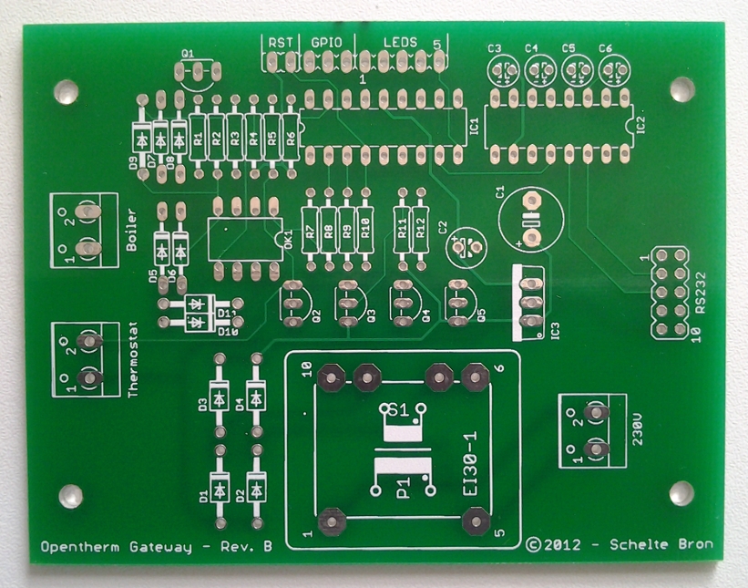
Print Layout
The printed circuit board for the gateway was ordered from a PCB manufacturing web site. The picture below shows how it came out.