Background information
I get many questions about the information the OTGW reports and how thermostats control boilers. Since I started working on the OTGW, I have read various information sources and looked at many logs that OTGW users have graciously provided. This page documents my current understanding of the subject.Messages
Communication between a thermostat and boiler that use the Opentherm protocol happens in the form of messages. An Opentherm message consists of 32 bits, layed out as follows:P TTT SSSS IIIIIIII DDDDDDDDDDDDDDDD
- P
- A parity bit. This bit is chosen so there is an even number of bits set to 1 in the message. This allows for the detection of a transmission error on a single bit.
- TTT
- The type of message. This table shows the possible values and their
meaning:
Request Response 000 Read-Data 100 Read-Ack 001 Write-Data 101 Write-Ack 010 Invalid-Data 110 Data-Invalid 011 111 Unknown-DataId - SSSS
- Spare bits. All 0.
- IIIIIIII
- Message ID. IDs below 128 are assigned by the Opentherm association. The rest may be used freely by manufacturers for test and diagnostic purposes.
- DDDDDDDDDDDDDDDD
- Message data. This can have several formats, depending on the message
ID. Some common formats are:
- f8.8
- Floating point value ranging from -128.000 to +127.996. Take the data as a signed 16 bit integer and divide it by 256 to obtain the floating point value. For example: Data value 0x15E1 = 5601 => 21.88.
- u16
- 16 bit unsigned integer, ranging from 0 to 65535.
- s16
- 16 bit signed integer, ranging from -32768 to 32767.
- u8
- 8 bit signed integer, ranging from 0 to 255. This applies to only one of the two data bytes. The other data byte may contain information in the same or a different format.
- flag8
- The bits of the data byte are used as on/off flags. To refer to a specific bit, the notation IDx:HBy/IDx:LBy is used, where x specifies the message ID, HB refers to the high byte, LB refers to the low byte, and y specifies the bit number within the byte (0..7). For example: ID6:HB1 refers to the 10th bit from the right in the data value of message ID 6.
The thermostat must send a request at least once per second and wait for a response from the boiler. If the response is received promptly, a thermostat may be able to send two or three messages in a second. Not all thermostats take advantage of this opportunity, and just send one message per second.
In general, when the thermostat sends a Read-Data request for a certain message ID, the boiler returns a Read-Ack response for the same message ID. When the thermostat sends a Write-Data request, the boiler returns a Write-Ack response for the requested message ID. When the boiler doesn't support a requested message ID, it returns an Unknown-DataId response. This can also happen if the message type is invalid for the requested message ID. For example: a Write-Data request for message ID 17, Relative modulation level, which is defined as a read-only message. When the boiler supports a requested message ID, but it does not have the information available, it returns a Data-Invalid response. This can happen when boilers can optionally be equipped with certain sensors, but that sensor is not installed.
Smart power
Upon startup, the thermostat keeps the line at a low voltage level in the idle state, and the boiler feeds the thermostat with a low current level. If the thermostat needs more power, for example for a screen backlight, it can use the Smart Power feature to make the boiler switch to a higher current level. It can also switch to a higher voltage level. This means that there are 3 possible power levels:- Low power
- Low voltage (8V) and low current (5mA). This is the normal power level.
- Medium power
- Low voltage (8V) and high current (17mA).
- High power
- High voltage (18V) and high current (17mA).
OTGW
The OTGW is normally placed in the connection between the thermostat and the boiler. In this configuration, the OTGW can operate in one of two modes: Monitor mode and gateway mode. The difference between these two modes is illustrated in the diagrams below:

- Monitor mode
- In monitor mode, the messages between the thermostat and boiler are passed transparently. No bits are modified. The presence of the OTGW does not introduce any delay. Because the communication does go through the OTGW circuitry, the signal levels are regenerated by the OTGW. But the timing is not affected.
- Gateway mode
- In gateway mode, the OTGW acts as a slave to the thermostat. In order to be able to provide most of the information requested by the thermostat, it will consult the boiler. The OTGW may also obtain the information requested by the thermostat from other sources, like serial commands or an external temperature sensor. Because the OTGW acts as a master to the boiler, it has the responsibility to send a message at least once per second. For that reason the OTGW still sends some request to the boiler, even if it obtains the information requested by the thermostat from somehere else. In gateway mode a 32ms delay (the duration of a message) is introduced in each direction by the OTGW, because it first has to collect the complete message before sending out a message on the other side.
There is another way the OTGW can be used; with only a boiler connected, no thermostat. This may be referred to as stand-alone mode. In that case the OTGW will act as a master and generate request messages to the boiler.
OTGW reports
Message reports
The OTGW reports the 32 bits of each Opentherm message it receives or sends as 8 hexadecimal characters with a 1 character prefix indicating which path the message travels. In gateway mode, these are the four possible paths and their prefix:- Thermostat to gateway (request)
- Gateway to boiler (request)
- Boiler to gateway (response)
- Gateway to thermostat (response)
Other reports
In addition to the messages, the OTGW can report a few other things:- Firmware version
- When the OTGW is powered up or resets, it reports its firmware and version. For example: OpenTherm Gateway 6.5
- Thermostat disconnected
Thermostat connected - The OTGW monitors the voltage on the thermostat interface. A thermostat that conforms to the Opentherm specification will have to keep the voltage below 18V. The OTGW interprets a higher voltage level as the absence of a thermostat. The OTGW switches to stand-alone mode when that happens.
- Low power
Medium power
High power - The OTGW supports Smart Power. When the attached thermostat changes the power level, this is reported by the OTGW. "Low power" is the normal power state. It is not an indication of a problem with the power supply of the OTGW.
- Error 01
Error 02
Error 03
Error 04 - If a received message does not conform to the Opentherm specification, the OTGW reports this as an error message. The error number indicates what kind of problem was detected.
- Command responses
- After a command is issued to the OTGW, the result is reported.
Reading the OTGW log
Conversations
A conversation between a master and a slave consists of a request from the master and a response from the slave. For a successful normal request/response exchange with an OTGW in the loop, the log shows the following messages:- A Read-Data or Write-Data request from the thermostat (the message has a T prefix).
- A Read-Data or Write-Data request to the boiler (the message has an R prefix). This report is suppressed if the OTGW did not alter the request in any way.
- A Read-Ack or Write-Ack response from the boiler (the message has a B prefix).
- A Read-Ack or Write-Ack response to the thermostat (the message has an A prefix). This report is suppressed if the OTGW did not alter the response in any way.
Central heating control
Controlling the central heating involves the following messages:- Message ID 0: Master and slave status flags
- Message ID 1: Control setpoint
- Message ID 6: Remote boiler parameter flags
- Message ID 14: Maximum relative modulation level setting
- Message ID 17: Relative modulation level
- Message ID 25: Boiler water temperature
- Message ID 57: Max CH water setpoint
When the control algorithm of a thermostat concludes that heating is necessary, it sets the CHenable bit (ID0:HB0 = 1). It also informs the boiler of the desired water temperature via the control setpoint (message ID 1) and the modulation range the boiler may use to achieve that (message ID 14).
When the boiler starts heating, it indicates that to the thermostat by setting the CHmode (ID0:LB1) and Flame (ID0:LB3) status flags. The boiler also reports the actual water temperature (message ID 25) and the modulation level (message ID 17) on request.
There are basically two ways for a thermostat to control a boiler: Temperature control and capacity control. The thermostat can switch between the two modes as appropriate, unless the boiler indicates that the thermostat must not use low load control (ID3:HB4). The two control mode are described in more detail below.
- Temperature control
- In temperature control mode, the thermostat controls the boiler water temperature using the control setpoint (message ID 1). It allows the boiler to use whatever modulation level it needs by setting the max relative modulation level to 100% (message ID 14).
- Capacity control
- In capacity control mode, the thermostat calculates a modulation level
and sends that to the boiler (message ID 14). It sets the control setpoint
(message ID 1) to the maximum value it obtained from the boiler (message ID
57) or some internal default.
This mode is most frequently used when even the minimum boiler capacity is more than what is needed at the time. In that case the max relative modulation level (message ID 14) is set to 0% to make the boiler run at its minimum capacity. The room temperature is then maintained by turning the boiler on and off over time at its minimum capacity, similar to how an old-fashioned on/off thermostat controls a boiler. This method of controlling a boiler is also known as low load control.
According to the experts, it is most efficient and most comfortable to have a boiler running constantly at a modulation level that keeps the house at the desired temperature. However, with most houses being well insulated now and the mild winters of recent years, most boilers are much too powerful, even at their minimum capacity. This means that thermostats will usually only use temperature control mode when the room temperature needs to be increased significantly.
Once the room setpoint has been reached, the temperature can normally be maintained at that level using low load control. To do that, thermostats generally have a fixed or configurable number of cycles per hour. Mostly 4 or 6 cycles are used. The amount of energy pumped into the house is then controlled via the duty cycle.
To continue the example from the note above, let's assume 2kW of energy is needed to keep the room temperature at the desired level. With the minimum capacity of the boiler being 5kW, a duty cycle of 40% would be needed. A thermostat that uses 6 cycles per hour would then turn on the boiler every 10 minutes and let it run for 4 minutes. Similarly, a thermostat configured for 4 cycles per hour would switch on the boiler for 6 minutes every 15 minutes. The duty cycle is adjusted as necessary by the thermostat's control algorithm if the temperature creeps up or slowly drops. This is another thing that confuses people. The thermostat may switch on the boiler when the room temperature is perfectly fine.
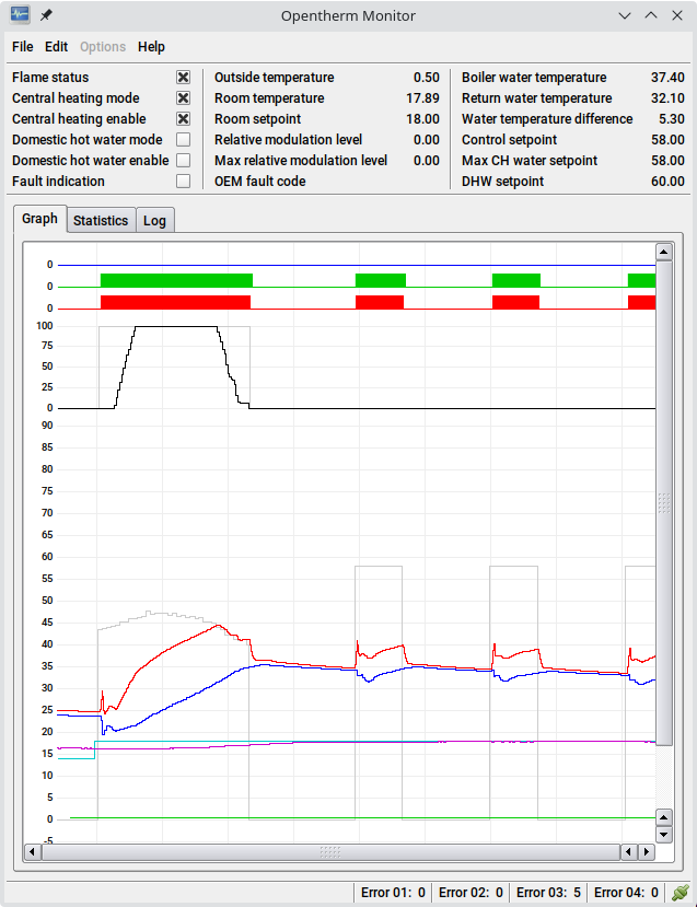 The two control modes can be observed in the graph on the right.
The first heating cycle happens because the room setpoint is raised from 14
to 18 degrees, while the room temperature is 16.33 at that moment.
The two control modes can be observed in the graph on the right.
The first heating cycle happens because the room setpoint is raised from 14
to 18 degrees, while the room temperature is 16.33 at that moment.
To bridge the temperature difference in a timely fashion, the thermostat uses the temperature control mode with a control setpoint starting at 43.39 degrees. Due to thermal inertia it takes some time before the heating results in an increase in temperature. Most thermostats use a PID controller to determine the control setpoint. The integral coefficient of the PID controller (the I in PID) causes the control setpoint to slowly increase while the temperature initially remains largely unchanged.
In the mean time the boiler ramps up its power to maximum. After a few minutes, the room temperature starts rising, reducing the difference between the room temperature and the setpoint, the error term in PID theory. This affects the proportional coefficient of the PID controller (the P in PID). A reduced error results in a lower the control setpoint. This continues until the boiler water temperature matches the control setpoint. At that point the boiler starts reducing its power in order to keep matching the control setpoint, which keeps going down as the room temperature continues to rise.
When the boiler has throttled its relative modulation level all the way down to 0% and the boiler water temperature exceeds the control setpoint, the thermostat ends the heating cycle.
The thermostat allows for an idle period for the temperature to stabilize. After some minutes, the room temperature is at 17.81 degrees. This small temperature difference can be handled by running the boiler at its minimum power. So this time the thermostat uses low load control. It runs a heating cycle of around 3 minutes.
10 minutes after the start of the previous heating cycle, the room
temperature is at 17.89 degrees. This means that the previous heating cycle
was not long enough to reach the room setpoint. For this reason the
thermostat runs the boiler slightly longer this time.
In fact, the duty cycle in low load control is also determined using a PID
controller.
Creating your own control strategy
The OTGW provides commands to manipulate the message IDs involved in controlling the central heating. This makes it possible to implement your own control strategy. There are many possibilities. Two frequently used strategies are discussed below.Weather-compensated control
In residences where there are multiple rooms to heat at a comfortable level, it may not be practical to let a thermostat control the heating based on the room temperature in just one of the rooms. In such cases a weather-compensated control strategy, or heating curve, may be implemented. This is a very simple control strategy, where there is an inverse relation between the outside temperature and the control setpoint. The colder it is outside, the higher the control setpoint.Basically two points are defined: A base point and a climate point. For each of these two points a combination of outside temperature and flow temperature is chosen. The outside temperature at the base point is normally around the desired room temperature. At that point the flow temperature is around the same value. For the climate point, the minimum temperature expected to be reached in winter is used. The appropriate flow temperature for that situation is then defined.
The most straight-forward method for determining a control setpoint is then just a matter of calculating where the current outside temperature lies between the climate- and base points. Then pick the flow temperature at the same position.
Example:
| Base outside temperature (Tbo) | 20°C |
| Base flow temperature (Tbf) | 20°C |
| Climate outside temperature (Tco) | -10°C |
| Climate flow temperature (Tcf) | 70°C |
| Current outside temperature (Tout) | 14°C |
Calculation:
Tflow = (Tbo - Tout) / (Tbo - Tco) * (Tcf - Tbf) + Tbf
Tflow = (20 - 14) / (20 - -10) * (70 - 20) + 20
This results in a control setpoint of 30°C.
It may be a bit too simple to use a straight line between the climate- and base points. For better results a function could be implemented that adds some degree of curvature to the heating curve.
Room control
A room control heating strategy bases the control setpoint on the room setpoint and the current temperature in the main living area of a house. This is the most commonly used strategy for controlling a central heating system. It is not covered first because it is much more complicated than the weather-compensated control strategy.A naive way to implement a room control strategy is to simply switch on the heating at a fixed control setpoint when the room temperature is below the setpoint, and switch it off when the room temperature is above the setpoint. But due to the feedback delay caused by the thermal inertia of a heating system, this will result in significant temperature swings around the setpoint. A refinement would be to adjust the control setpoint based on the difference between the room temperature and the room setpoint. But this will still not reduce the temperature swings enough for a comfortable in-house climate.
For better temperature control, most thermostats implement a PID controller.
The name refers to the tree components of the controller: Proportional,
Integral, and Derivative. These tree components are each assigned a weight
and then added together.
Applying PID theory to room control, the "process variable" is the room
temperature and the "set point" is the room setpoint.
The difference between these two is referred to as the "error term".
The proportional component of a PID controller is easy.
In fact, the refined naive control method described in the previous
paragraph corresponds to the proportional component of a PID controller.
The integral component of a PID controller sums the error term over time.
The derivative component relates to the rate of change of the process
variable. On a slow control loop, such as in a central heating system, the
derivative component can easily make the system unstable.
The only time there can be a big change in the error term is when the room
setpoint is changed. But that is no reason to start heating excessively.
For that reason the weight of the derivative component is generally set very
low, or even to 0. That effectively turns the PID controller into a PI
controller.
Calculating the PID output seems deceptively simple. Take a temperature reading (Tr) at regular intervals and then run the pseudo-code below to calculate a control setpoint (Tset):
error = TrSet - Tr
integral = integral + error * interval
derivative = (error - last_error) / interval
last_error = error
Tset = Kc * error + Ki * integral + Kd * derivative + bias
When opting for a PI controller instead of a PID controller, the gray parts can be omitted, making the code even simpler. The difficulty with a PID controller is tuning, in other words: Determining the optimal values for Kc, Ki, and Kd.
Kc is called the controller gain. It can be calculated from the process gain Kp, time constant Tp, and dead time Өp:
-
Kc = 1/Kp * Tp / (Өp + Tc)
When measuring the interval in seconds, a Ki of 0.02 will add 1.2 degrees per minute to the control setpoint for each degree of temperature difference (0.02 * 60). That is roughly the figure that should provide a reasonable result. If the room temperature never reaches the room setpoint, increase Ki. If the room temperature overshoots the room setpoint and oscillates around it, decrease Ki. When initially tuning Ki, use a factor of 2 to adjust it up or down. So, to increase Ki, double it. To decrease Ki, halve it.
For central heating applications it is best (and certainly easiest) not to use the derivative component. So, just forget that part, or use a Kd of 0.
Simply adding the weighted components of the PID controller together produces a value that is positive when heating is needed and negative when not. This cannot serve directly as a control setpoint. A bias value needs to be added to lift the value to a level that will actually cause the boiler to start heating when used as control setpoint. A bias value of 20 should do.
The PID calculation described above is known as the independent algorithm form. Another popular PID algorithm form is the dependent, ideal PID controller. This form uses different tuning parameters, Kc, Ti and Td. Kc is the same in both forms. Ki = Kc/Ti. Kd = Kc * Td. In this form, the tuning parameters interact with each other. This makes tuning more challenging.
Complications
That all sounds quite doable on paper, but in reality there are some complications.- Physical limitations
- The boiler is not able to produce any flow temperature that may be requested via the control setpoint. The boiler may refuse to start when the control setpoint is too low. Or if it does start, it will quickly reach the requested flow temperature and switch off again. Such short bursts will not produce any useful heat, while still causing wear on the boiler and needlessly burning gas. So the control algorithm should prevent these situations. One possible way to resolve this is to implement low-load control.
- Integral windup
- There are times when the boiler is unable to take care of producing heat
to the central heating system. Somebody may be taking a long shower or
running a bath. The boiler can also be unplugged for periodic maintenance.
If the room control algorithm continues as normal during these times, the
integral component may increase to a very high value. When the boiler can
start heating again, it will take a long time for the integral component to
get back to normal levels. This may cause a huge overshoot.
The opposite may happen when the room setpoint is lowered at night or during absence. As a central heating system does not actively cool the house, it may take a long time for the temperature to drop to down the setpoint. In the mean time the negative error keeps accumulating in the integral component. This results is a slow response when heating is needed again.
Several anti-windup methods have been invented to deal with this. The simplest is probably to put limits on the integral component. Additionally, accumulating the integral component can be suspended when the boiler is in DHW mode and when it stops sending responses. - Unsupported messages
- Not all boilers support all Opentherm messages needed for the best possible control of the central heating system. It may for example not provide the max CH water setpoint (message ID 57). Even worse, some boilers don't support the maximum relative modulation level setting (message ID 14). This eliminates the possibility to use the capacity control mode with these boilers. That makes especially low-load control much more tricky than it has to be.
Low-load control
When heating is required, but the control setpoint determined by the control algorithm is too low for the boiler to start heating, or it would only run for a very short time, a different strategy is needed.For low-load control, a fixed number of heating cycles per hour is chosen. 4 cycles per hour is a reasonable number. With 6 cycles per hour, the room temperature can be kept at a more constant level, which can be perceived as more comfortable. It does cause more wear on the boiler. During each cycle the boiler is instructed to run at its minimum capacity (max relative modulation level = 0, control setpoint = maximum) for some time, then switched off for the remainder of the cycle. The duty cycle is again calculated using a PID controller. This can be the same PID controller that is used for determining the control setpoint, because it involves the same process variable and set point values as input. It just needs a suitable conversion from control setpoint to duty cycle. This can be a linear conversion, where the bias value equals 0% and something like 45°C equals 100%. That may seem low, but at that point it is probably time to switch back to temperature control.
Also with low-load control it should be avoided that the boiler will only burn for a short while. So if a duty cycle is calculated that puts the on-time below a certain threshold, say 2 minutes, the cycle time should be stretched. For example, a duty cycle of 8% is wanted. With 4 cycles per hour that would result in an on-time of 72 seconds. If a minimum on-time of 2 minutes is chosen, the cycle time must be stretched to 25 minutes. 2 minutes out of 25 minutes is the requested 8%.
When a boiler doesn't support the maximum relative modulation level setting (message ID 14), a much more tricky method is needed to keep it running at its minimum capacity: The control setpoint (message ID 1) must first be set high enough for heating to start. Once that is achieved, the control setpoint must follow the boiler water temperature (message ID 25). This requires frequent updates of the two messages. If there is too much time between updates, the water temperature may rise too far above the control setpoint, causing the boiler to switch off.